
Die Design & Filling Simulation
Die Design & Filling Simulation
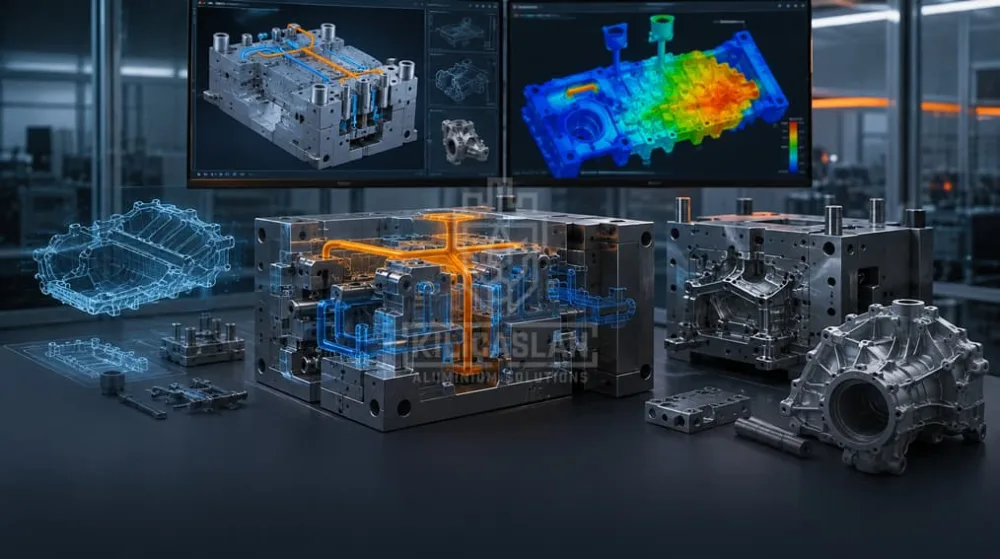
Runner and cooling design verified by filling and solidification analysis before the first trial.
Die design and filling simulation is the stage where the fate of an aluminium die casting is decided. Kılıçaslan does not outsource it: our own engineering team designs the runner system, the cooling circuits and the venting, and verifies filling and solidification on screen before any die steel is cut. The goal is simple — the first trial shot should already be acceptable.
Why simulate before the die is cut?
The die is the most expensive and the slowest item in a casting project. Every correction after the steel is cut costs both material and calendar time. Filling simulation moves that risk forward: how the melt advances through the cavity, where air will be trapped, which region solidifies last and where hot spots form are all visible while everything is still a model.
Simulation returns filling time, solidification time, local flow velocities, die temperature distribution and micro-porosity tendency. Those outputs feed directly into gate position and cross-section, which is what shortens the run-up to a good part.
The decisions we make in die design
Parting line and draft angle
The parting plane determines where the flash line falls and which way the cores move. Where draft is insufficient the part drags on ejection, scores, or sticks in the die. We explain the reasoning in why draft angle matters in die design.
Runner and gate design
The gate cross-section sets filling speed and turbulence. Too small and the melt cools early, leaving cold shuts; too large and the flow becomes disordered and drags air in. Gate position is also chosen so it can feed the region that solidifies last.
Venting and overflows
The air in the cavity has to go somewhere. Vents and overflows carry trapped air and the first cold metal out of the part. Good venting removes most of the porosity problem before it appears.
Cooling circuits
The thermal balance of the die controls both cycle time and dimensional stability. Channels are brought close to hot regions while thin sections are protected from overcooling. An unbalanced die produces a part whose dimensions drift from cycle to cycle.
What you receive from the design stage
- Castability report — wall thickness transitions, draft angles, sharp corners and mass concentrations
- Runner and venting layout — gate position, cross-sections and overflow placement
- Filling and solidification analysis — flow front, air entrapment zones, hot spot map
- Cooling layout — channel routing and expected cycle time
- Die general assembly — core movements, ejector layout, block dimensions
What happens next
The approved design goes straight to our own tool room; no intermediate supplier is involved. See Die Manufacturing. Once the die is running, the part is produced on our high pressure die casting line.
If you have no 3D model, we can start from an existing sample through reverse engineering and prototyping.
Why Kılıçaslan
- Design and casting in one team. The engineer who designs the die also sees how it behaves on the press.
- Simulation is standard, not an option. Filling and solidification analysis is run on every new die.
- Early warning. If a geometry is not suitable for casting, we say so at quotation stage and propose an alternative.
- One archived data set. Design, simulation report and manufacturing drawings are stored together for later revisions.
Frequently asked questions
Which file formats do you work with?
Common neutral solid formats such as STEP and IGES are enough. If you only have 2D drawings we can build the model; if you only have a physical sample we start with 3D scanning.
Is simulation needed for every part?
For a simple, thick-walled part experience is often sufficient. For thin walls, long flow paths and parts that must seal or be welded, simulation measurably reduces the number of trials. We run it as standard.
Will you propose changes to my part?
Yes. Most casting problems can be solved with a millimetre of change in the part itself. We present the reasoning and leave the decision to you.
Is die design charged separately?
Design and simulation are included in the die quotation. A design-only engagement is assessed separately.
Send your drawing through our contact page for a castability review.
Get information about this service
Our expert team is ready to offer you the best solution.